The Maple Valley Short Line Model Railroad is operational. I have been running trains on the main lines without any major interruptions or catastrophes. From the moment I first drilled holes in the cement blocks, to securing the last piece of HO scale flex-track, this has been an enjoyable journey. But the journey is far from over.
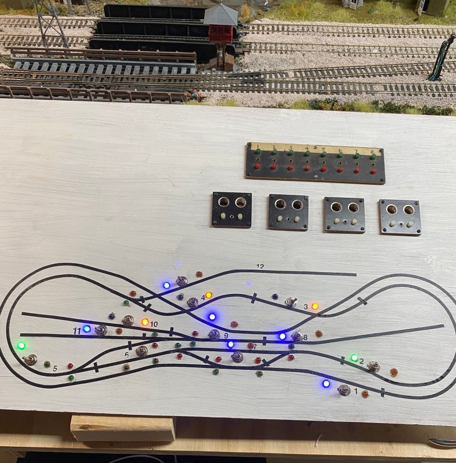
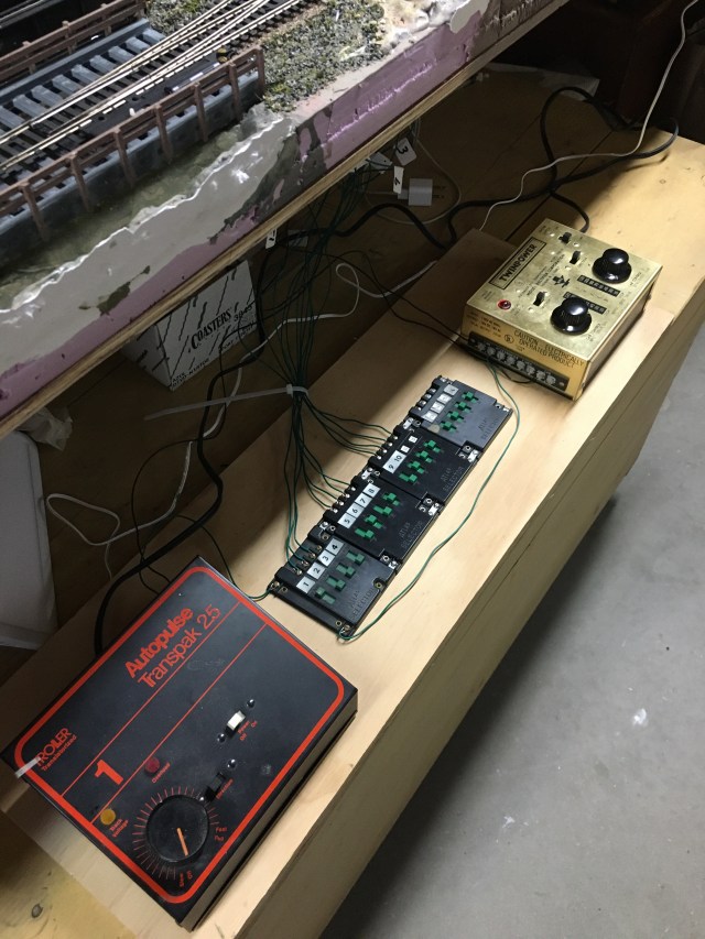
The simple control center in the photo supplied power to run tests on the layout. Although I have always used Atlas Selectors (four blocks of four switches) in the past, I am building a control panel with DPDT (double-pole, double-throw) three-position toggle switches to direct power to the layout.
I will use indicator LEDs on the control panel. I plan to have a signal LED on each spur as well as a direction indicator on each turnout. Atlas Snap Relays will be used for each turnout to control track signals at the turnout and an indicator LED on the control panel.
My layout control panel base is a thin (3/16″) piece of plywood. I first drew the track plan on the wood with a pencil. (I actually did it twice as the first one wasn’t large enough.) I covered the pencil lines with 1/8″ artist tape which bends easily and sticks securely to the board. The short cross pieces of tape indicate where the rail gaps create blocks. I chose to make the mainline a single block. With the same layout design, you might choose to do otherwise. But with only one way to and from the outside main line, I didn’t think a shorter block was necessary.
I will place an LED on either side of each toggle to indicate if the spur is powered, and which cab is operating it, A or B. Two LEDs at each turnout will indicate direction.
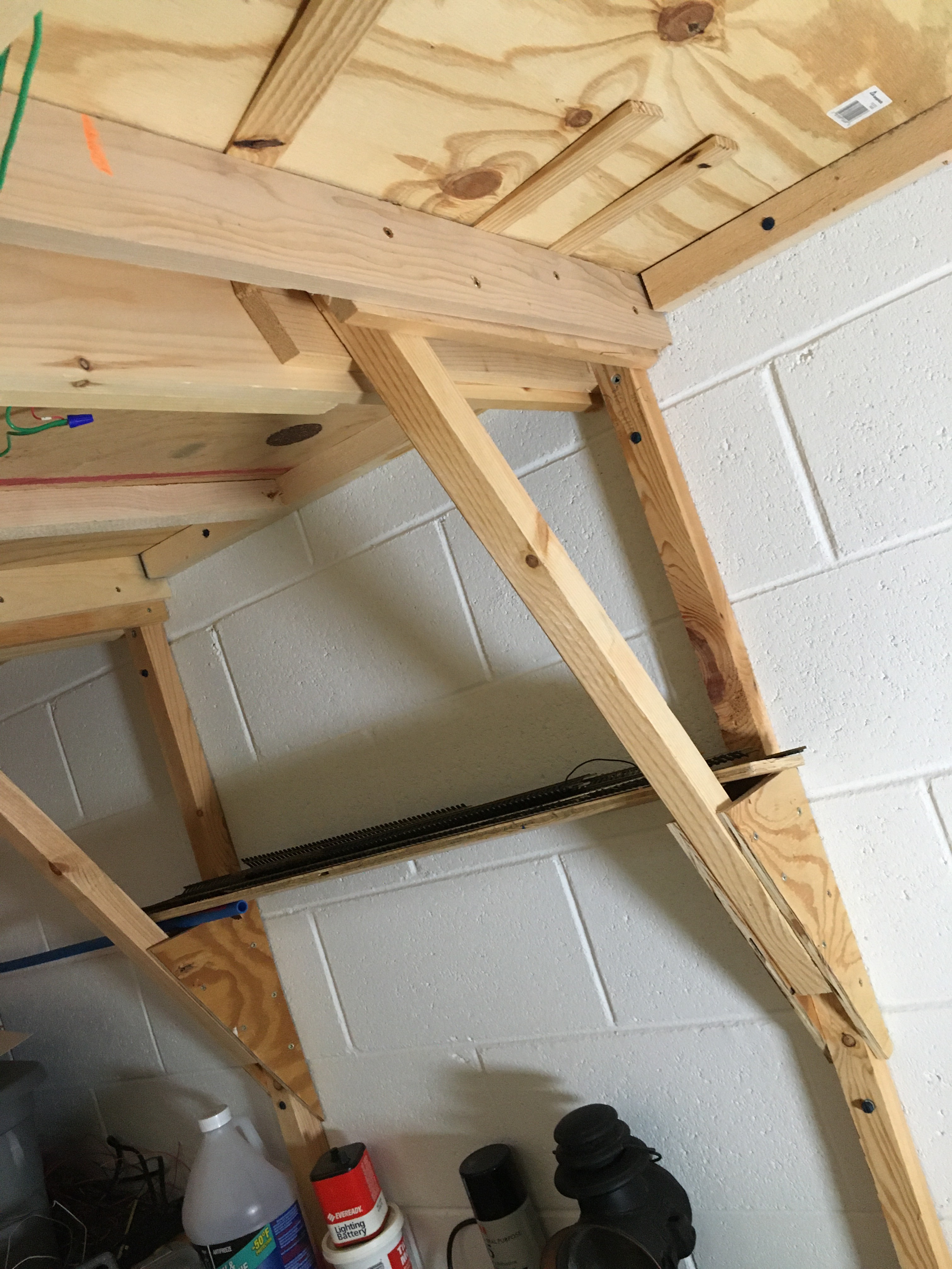
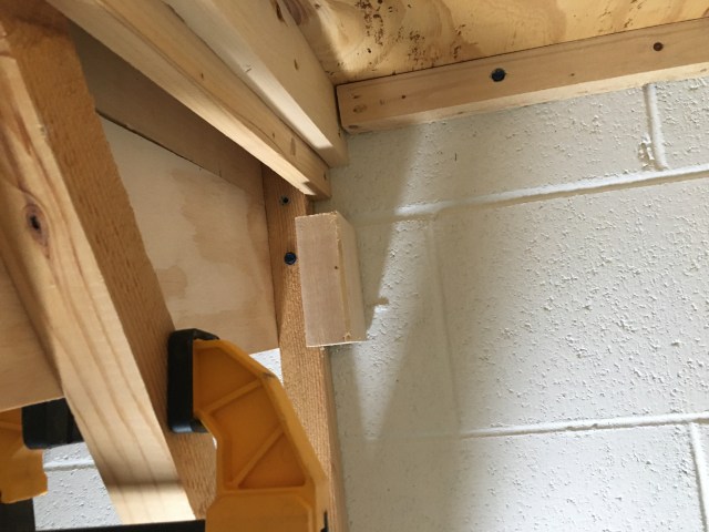
I first had to decide how best to attach support for my control panel to the benchwork. I could have attached support to the layout joists, but chose to use the bracket legs instead.
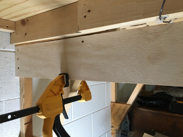
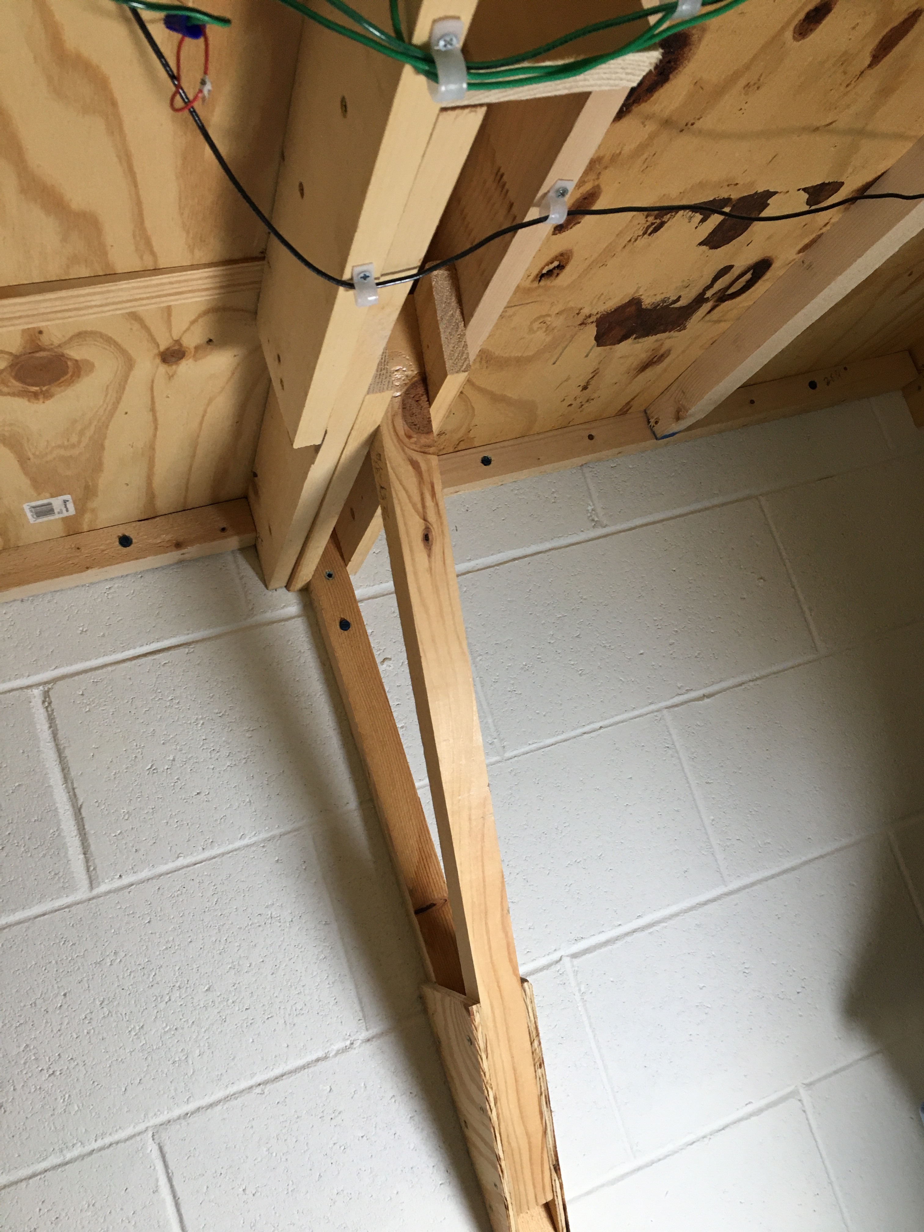
I cut two pieces of 3/4″ plywood, 5 1/2″ x 49″. The plywood supports extend sixteen inches beyond the outside edge of the layout, allowing plenty of room for the control panel. I secured the supports with three 2 1/4″ screws through each 2 x 2 leg brace. A block of 2 x 4 behind the leg brace supplies plenty of strength to hold the panel support in place.
I made the same mistake on my previous layout. I didn’t think about the control panel as I was building the benchwork. I had a general idea where I wanted it but didn’t plan ahead by adding supports. I am confident the plywood will hold the control panel safely, but it would have been better to design the structure before, not after.
I finally received the three-position, double-pole-double-throw switches I want to use for the control panel. Before I decided how to proceed, I watched a lot of videos by the best model railroaders to see what kind of control panels they designed. Some modelers use plexiglass, others prefer aluminum, there are some who use computer aided design, all of which are impressive. I chose to go simple and basic.
I am actually going to use the DPDT switches as two single-pole-double-throw switches. One side will be DC, the other side AC. DC will obviously power the railroad spurs by supplying current from either cab A or B, determined by which way the toggle is thrown. The other side will supply AC power to LEDs to indicate the spur is live, and which cab is supplying power.
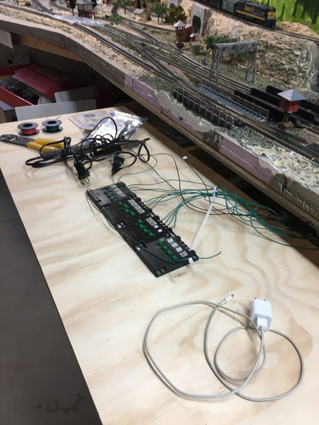
For the time being, the space is perfect for the new round of soldering that will soon begin. Even though the Atlas Selectors provide a workable solution for dual-cab operation, for this, my third layout, a better plan is underway. My new panel will have lots of LEDs to light up the controls.
Future posts will include details on wiring and soldering progress on the Maple Valley Short Line.
News to come:
- Running wires for turnouts
- Building more signals
- Placing signals along the layout
- Attaching Atlas Snap Relays under the layout
- Scenery progress
- Ballasting
If you have comments or suggestions, please let me know. Tell me about your experiences with model railroading.
