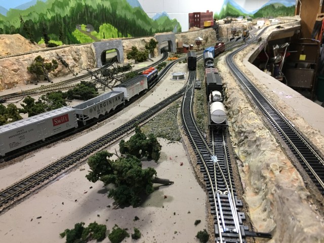
The Maple Valley Short Line is the largest HO scale model railroad I have ever built. My first was a free standing reverse-dogleg L-shaped layout. It was a learning experience, as all layouts are. I took it apart and moved it twice before finally cutting it apart for the last time.
My second model railroad was a shelf-style layout that was sixteen feet long, three feet deep at the ends, two feet deep in the middle. I didn’t use cork roadbed so the 3/8 inch plywood base doubled as a soundboard for the rolling trains. I used common-rail wiring with Atlas Selector Switches so I was able to run two trains simultaneously. I prefer a loop design so trains can run constantly rather than point-to-point.
After nine years in that home we moved again so it was time to dismantle another layout. I thought this would be my last model railroad and it was time to hang up my engineer hat. (Yes, I really do have one.) Rather than removing all the benchwork, I left it in place with a bunch extra model railroad gear for the young boys who would soon move into our house.
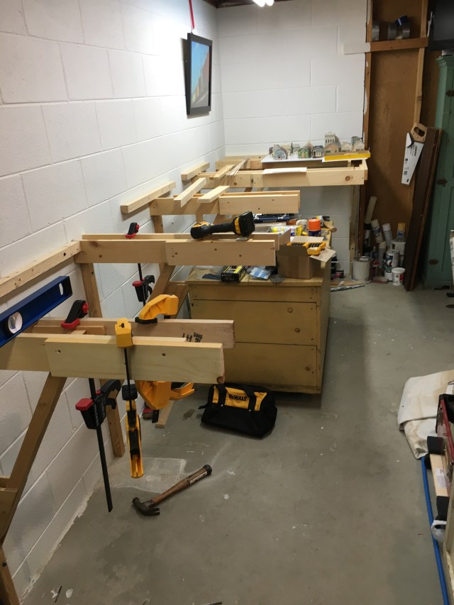
Much to my surprise, the new home we decided to purchase had a long rectangular room in the basement just like our previous house, only bigger. After almost a year in our new house I decided to build another layout, the Maple Valley Short Line. I was then surprised to learn the new owners of our old house decided to remove the benchwork I left and offered to give it to me. That meant I had most of the leg brackets and plywood I needed for a new layout, free!
I started construction on the Maple Valley Short Line three years ago. I started with the difficult task of drilling holes in cement blocks requiring a new masonry bit after just three holes. I fastened leg brackets to the wall, attached plywood and extruded foam for the layout base. Through all the other steps of creating a model railroad, the MVSL is looking great!
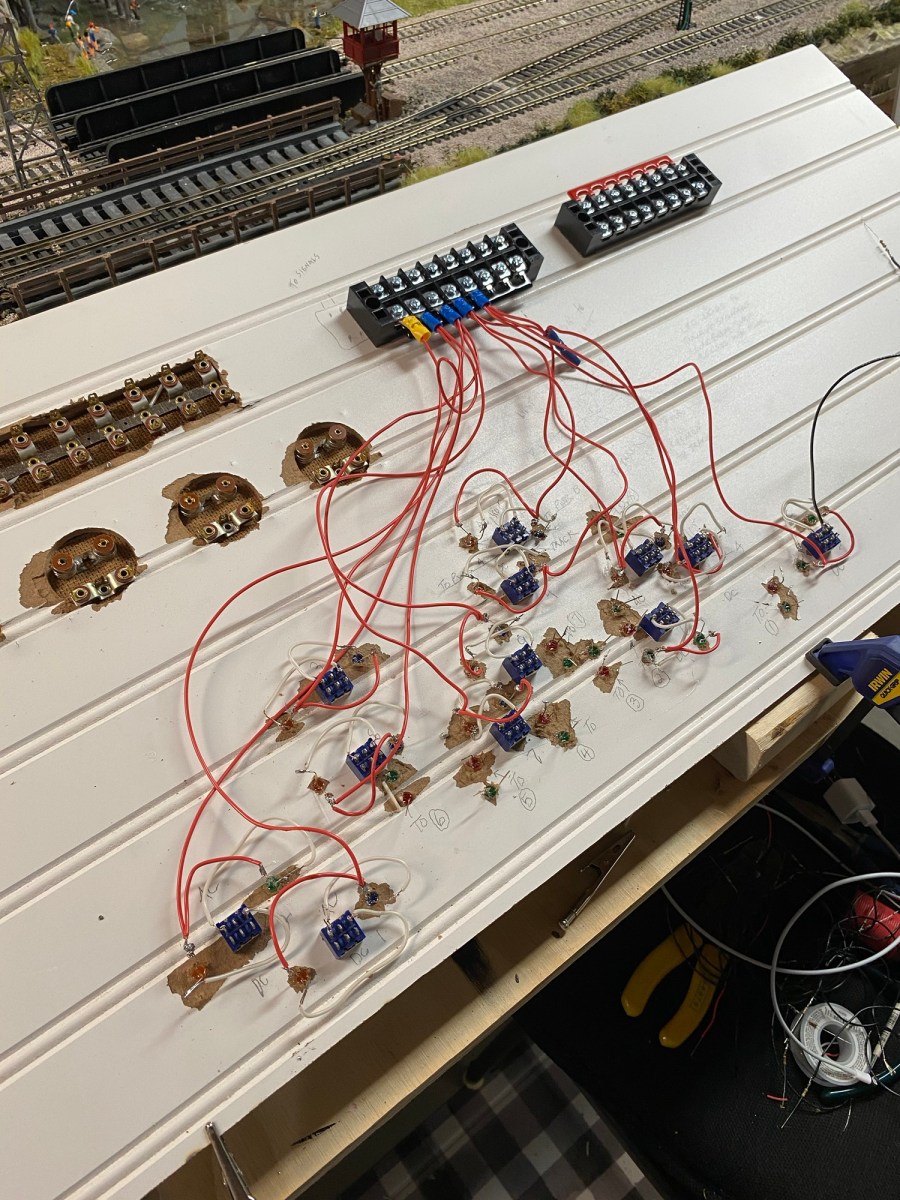
I encourage readers to catch up by reading other posts covering my progress on the Maple Valley Short Line. Wiring any layout is a very important step regardless of size, and I have studied detailed schematics to make sure I get it right. The great thing about wiring is if I do make a mistake, fixing it is much easier than moving a plaster mountain or a stretch of track.
I battled with the decision between using Double-Pole-Double-Throw (DPDT) toggle switches or my standby Atlas Selector Switches which I have always used before. DPDT toggle switches have six posts which require attaching wires with solder. Multiply six posts by fourteen switches and that’s eighty-four solder points just for block power. Atlas Selector Switches contain four center-off DPDTs. (Blocks are electrically isolated sections of the layout wired separately with a choice between power supplied from Cab A or Cab B. I will actually have three cabs (power supplies), two for mainlines and one dedicated to the Maple Valley Passenger Line which is point-to-point.)
Why use blocks, you may ask? Experts advise blocks should be as long as the longest train operated. Blocks allow engineers to move trains on the same track simultaneously under separate control. The DPDTs have a center-off option that shuts off power to the block so, for example, cars can be positioned by a smaller switch locomotive running outside the “power-off” block. The operator has the choice of using Cab A or Cab B for each block.
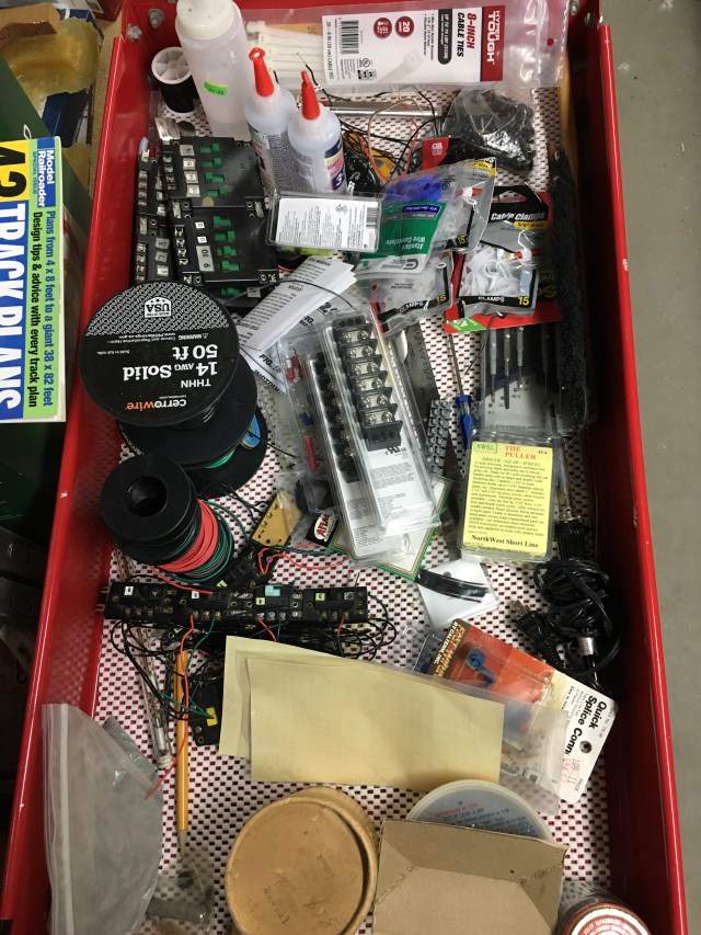
Before starting the wiring project, I checked to be sure I had everything I needed. My work tray in the photo is a wheeled two-shelf tool cart I keep nearby for each phase of the project. As you can see, it’s now filled with electrical supplies.
There is an important difference between common-rail wiring and totally isolated block wiring. Common-rail means one rail of the track has continuous connection throughout the layout. There are no breaks in contact since nickel-silver rail joiners are used to join each rail section. The tricky thing is making sure the rail you choose is the same for the entire layout. That can get confusing if you have a lot of turnouts. Since the rail is continuous, only one connection to the power source is needed. If you are using two cabs, the common rail will be connected to both cabs so the cabs are connected to each other.
After deciding where the blocks will be, gaps in the rail or plastic rail joiners are used at each end of the blocks. The remaining DC outputs on the two cabs are connected to the Atlas Connector Switch, side A or B. Then from each of the four posts on the Atlas Connector Switch, wires are run to each of the blocks and soldered to the rail opposite the common rail. Each connector switch can control four blocks. Additional switches can connected to each other. Fewer wires, easier job.
On the Maple Valley Short Line, I chose to use completely isolated blocks which means both rails are either gapped or separated by plastic rail joiners. I use plastic joiners.
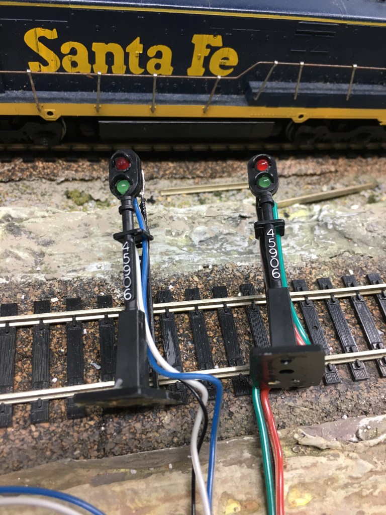
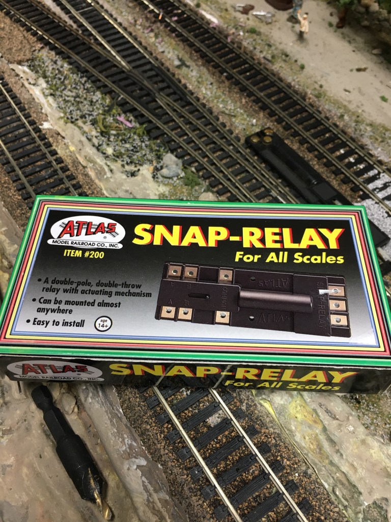
I will be using two-light signals at the turnouts which will indicate which direction the rails are set. I made the signals by replacing the stock lenses with operating green and red bulbs. I soldered a resistor to one wire and will attach each signal to the turnout and Snap-Relay, powered by the AC side of the cabs. I am also going to include red and green indicator lights on my control panel.
In Wiring the Maple Valley Short Line, Part 2, I will include photos of the underside of the layout with power routing to blocks and signals.
Happy Model Railroading!

Pingback: The Model Railroad Control Panel is Finished! – A Coffee State of Mind