
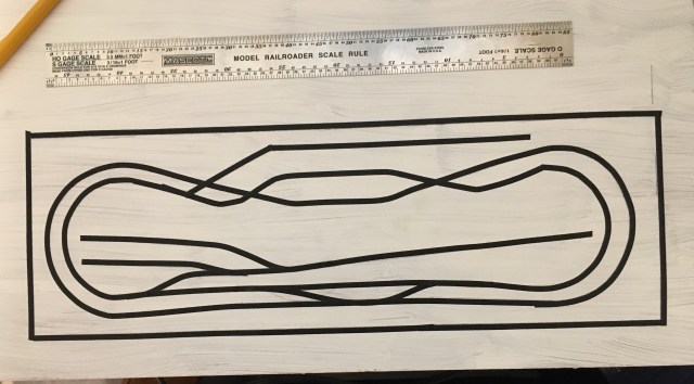
I began working on the control panel for my HO scale Maple Valley Short Line Model Railroad five years ago. My initial step was to create an outline of the layout using 1/8″ artist tape. The first one was too small, so I had to do the tape project over again.
I chose to build a control panel and stop using Atlas Selector switches. They work fine, but I wanted to have an outline of the layout with indicator LEDs for blocks and turnouts.
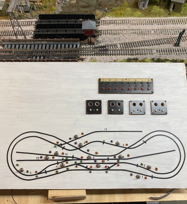
I should have made the layout diagram even larger. By the time I installed the LEDs, space was tight. I knew the close proximity of the switches meant soldering wires on the back was going to be difficult. Making the task even more challenging is the fact I have essential tremors. When I try to do something requiring steady hands, my hands decide it’s time to dance.
If you are unfamiliar with terms like turnouts, blocks, and selectors, click on the links for more information.
Efficient use of space on the control panel is possible thanks to three-position-double-pole-double-throw switches. The big question was whether direct current and alternating current can flow through the switch at the same time. Locomotives operate on direct current running through the track. Accessories, including turnout switch machines, trackside signals, building lights, and signal LEDs on the control panel are all powered by alternating current.
The DPDT toggle switch has six small contacts on the back. I used a continuity tester to determine whether my plan for the DPDT switches was a disaster waiting to happen. As it turned out, the two sets of three contacts are independent, so, theoretically, AC and DC can flow through the same switch.
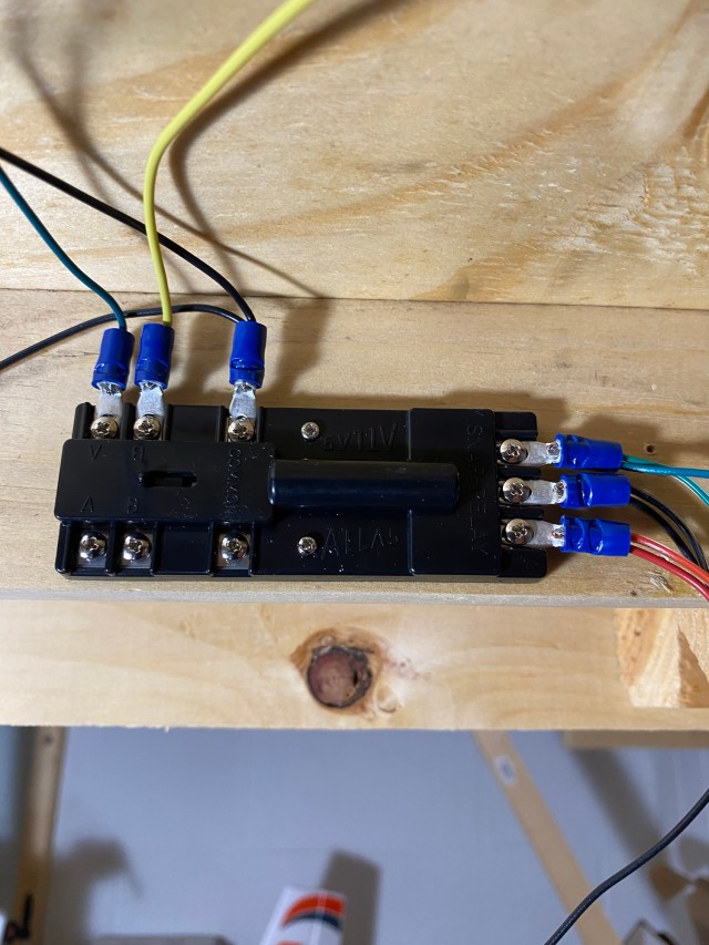
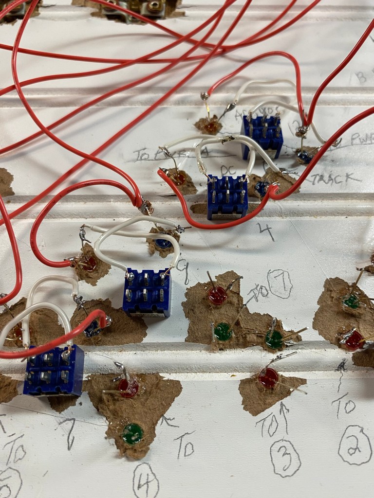
Before going on, I must talk about the Atlas Snap Relay. I have never used the relays before, and I had a difficult time understanding how they work. I studied the schematics and also found helpful information online.
Three vertical contacts relay AC power from momentary contact buttons on the control panel to turnout switch machines. The three horizontal contacts on top relay power to the trackside and control panel LED signals. A red or green signal depends on which control panel turnout button is pushed.
My confusion was finally resolved by realizing the three sets of contacts on the relays are independent of each other and each requires a power supply. Three vertical and top horizontal contacts are connected to alternating current (AC). The bottom horizontal contacts can be connected to direct current (DC) to power turnout frogs and sidings. I chose to use direct block wiring for sidings instead of the relays.
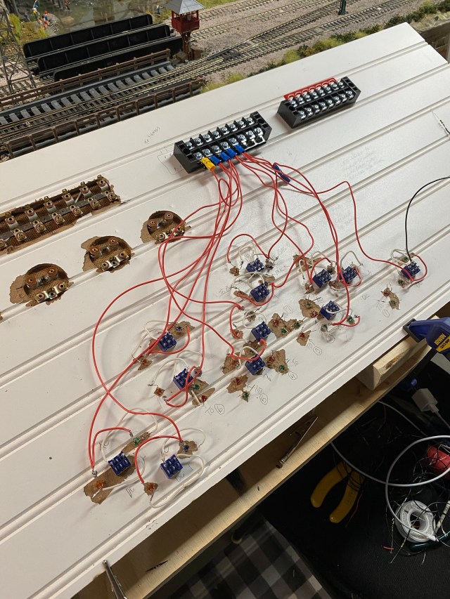
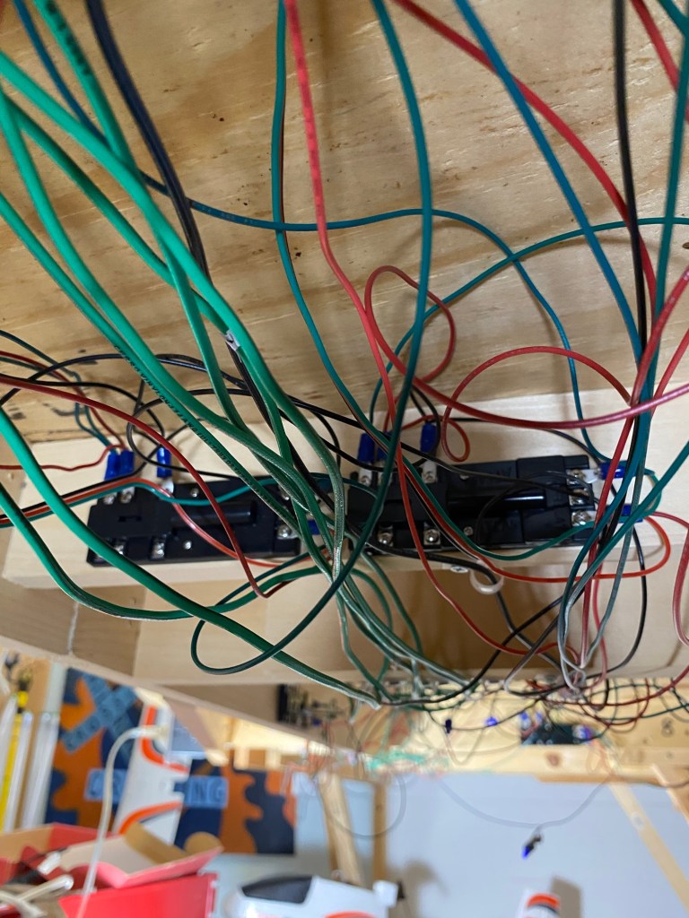
The underside of my control panel is not pretty. Using wainscoting material was a mistake. It was impossible to drill clean holes through it, but I pressed on rather than starting over. As my wiring project continued, it also grew. It seemed like each completed connection created a new one. Each wire represented questions whether my control panel would actually work. I pictured cutting it loose and going back to simple wiring without fancy lights and switches.
My layout has twelve blocks requiring isolated wiring. Twelve blocks meant twelve DPDT switches, each with six contacts, so I had seventy-two connections to solder. Each DPDT switch is connected to two LEDs, each with two leads, so that added forty-eight more contacts to solder in a very small space. The longer I thought about it, the more my hands danced.
I have eight turnouts on the layout. Each turnout has two LEDs on the control panel to show which way the turnout is set, either to the mainline or the siding. That adds another sixteen LEDs, so an additional thirty-two contacts to solder. Each of the LEDs requires a resistor to reduce the voltage. Without a resistor the LEDs pop like an old-fashioned flash bulb. That’s another forty solder points. By this time, my hands were doing the cha-cha, the foxtrot, and the Wild Horse Saloon line dance.
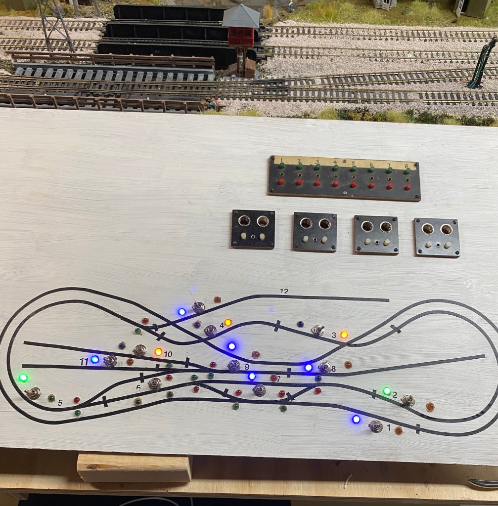
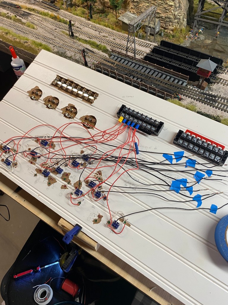
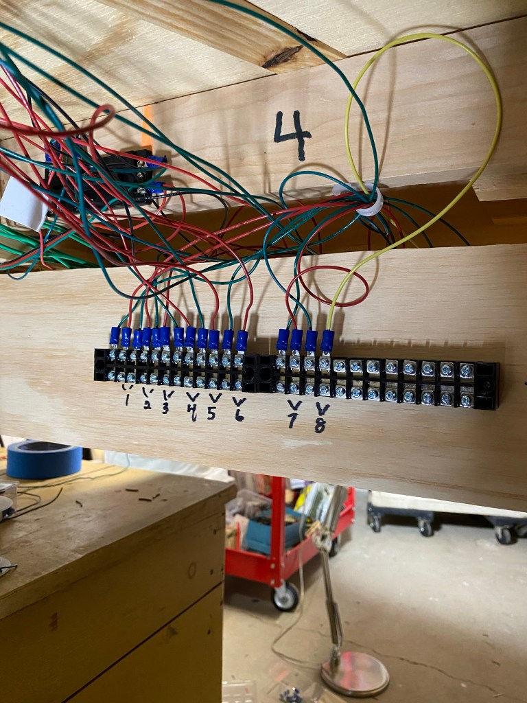
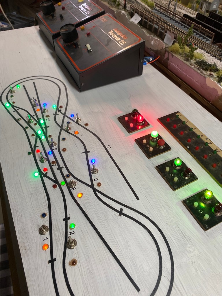
I had the foresight to check LED connections one step at a time, so I did receive some incremental rewards when they actually worked. In the middle photo, the terminal strips on top supply DC power to the twelve blocks, and AC power to all LED positive contacts. The terminal strip on the lower right supplies positive DC power from the transformer (Cab A) to the DPDT switches. The strip on the lower left supplies positive DC power from the transformer (Cab B) to the DPDT switches. Toggling the DPDT switch left or right directs which cab is supplying power to the block.
To avoid confusing the DPDT contacts, each switch is attached to the panel in a horizontal position. The top set of three contacts are AC, the bottom contacts are DC. The positive LED contacts are connected together by jumper then to the positive AC terminal strip. The positive power feed is constant. The negative LED contacts are connected to the outside DPDT contacts. The middle DPDT contact is connected through a resistor to the negative AC terminal strip. The LED circuit is completed on the negative side by the toggle switch’s movement, left, right, or center (off).
On the DC side of the DPDT switch, the two outside contacts are connected to the DC terminal strips right or left. The right terminal is powered by transformer Cab A. The left terminal is powered by transformer Cab B. The center DPDT contact is connected by wire to a terminal strip located under the layout benchwork.
My use of DPDT switches with AC and DC is only possible because I use what is known as “common rail wiring”. Common rail wiring means the negative feeds from both transformers, Cab A and Cab B, go directly to the track rather than through the DPDT switches. The trick is making sure the same rail throughout the entire layout is connected to the negative feeds. The DPDT connects the positive DC feed to each block on the layout, from either of the two cabs, depending on which way the toggle switch is set, left, right, or center (off).
The last major wiring project was the momentary contact buttons which control switch machines on the turnouts. Once again, turnouts provide an option for the train to continue on the mainline or turn onto an alternate route like a siding. I have four vintage Acme push buttons with indicator lights, and a strip of sixteen buttons. My turnouts have snap machines rather than slow-motion tortoise machines. When a button is pushed, the machine snaps the track points one way or the other.
I followed the wiring schematic for the Atlas Snap Relays, connecting the center contact on the relays to the center contacts of all switch machines, then to the common contact on the push buttons. I connected the two remaining contacts on the relays and switch machines with the push buttons.
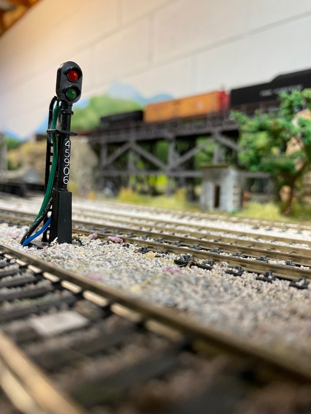
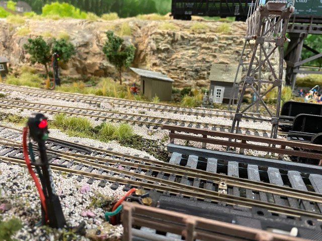
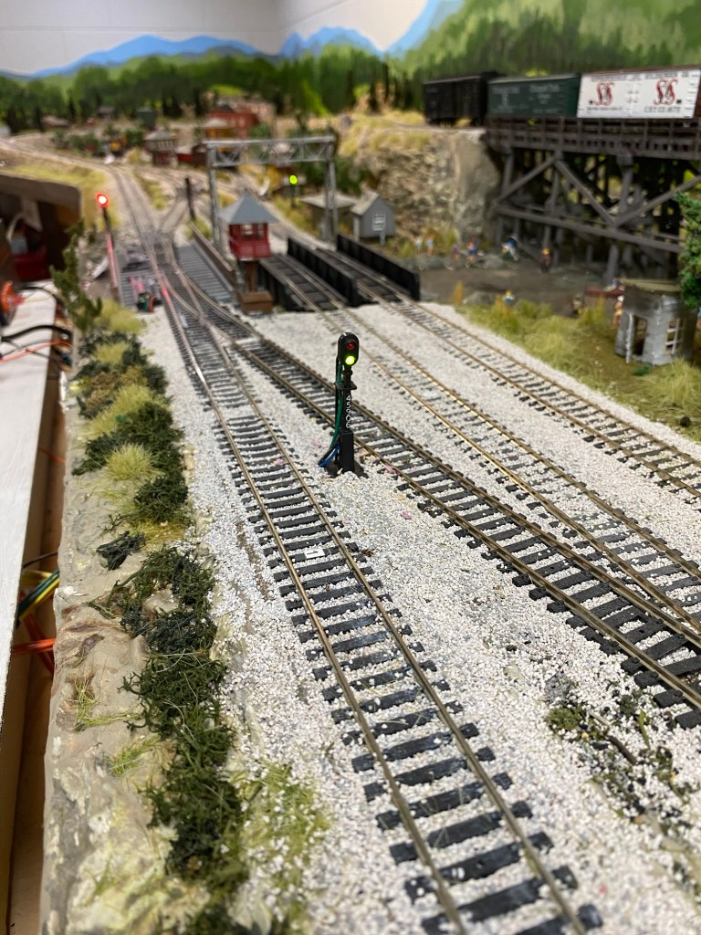
Red and green LED signals on the control panel indicate which way turnouts are set. There are scratch-built trackside signal towers with red and green LEDs near each turnout working the same way. When the turnout control button is pushed, the signal lights change from green to red, and the switch machine snaps the track points to the siding. That’s if my plan works perfectly.
After finishing all the wiring on my control panel, nearly three months passed before I began making final connections under the layout. I added twenty-four inches of wire to the panel terminal blocks so I would have plenty of length to make connections to the terminal blocks under the layout.
At seventy-two years old, three months is plenty of time to forget what I was thinking when I labeled the dozens of wires hanging out the back of my new control panel. It took me a couple hours, quietly sitting under the layout, staring at the leads and contacts, trying to remember what numbers and letters meant. Finally, each step began to fall in place.
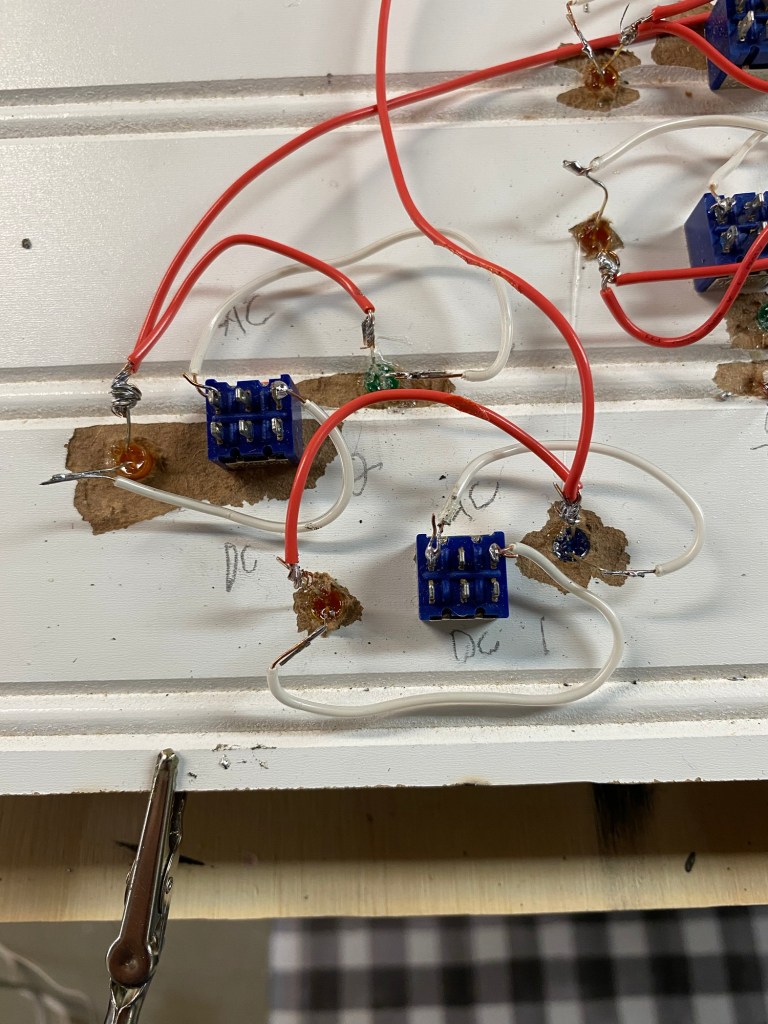
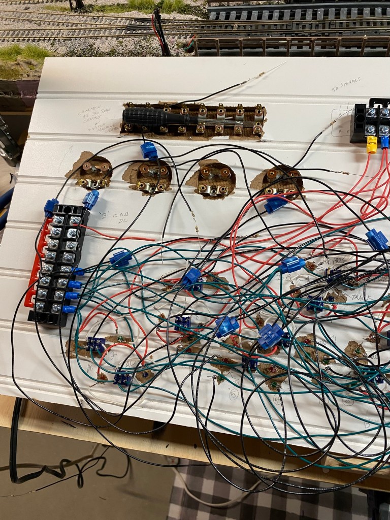
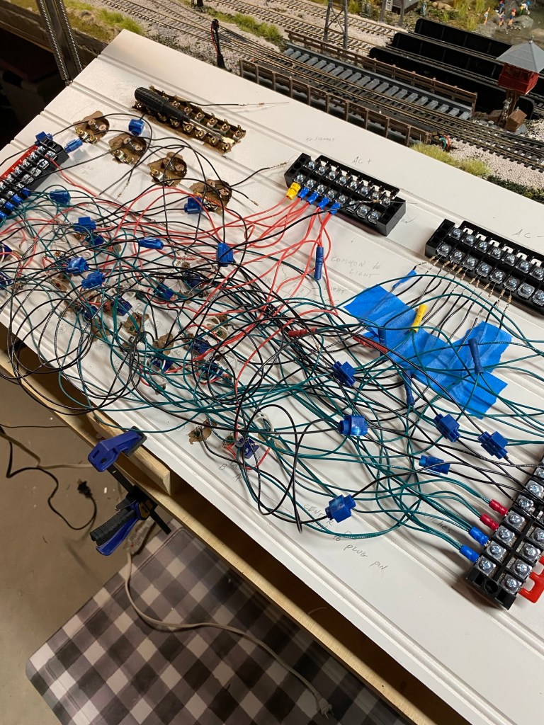
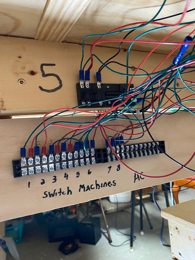
The terminal strips designated “Switch Machines AC” show wires connected to the Atlas Snap Relays and turnout switch machines on the layout. The terminal blocks with contacts numbered 1-8 show wires connected to the snap relays, trackside signals, and control panel signals. The last photo shows two Atlas Snap Relays with completed wiring. Final wiring will connect leads from the control panel.
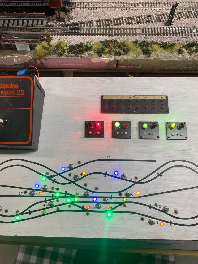
The control panel for my HO scale Maple Valley Short Line Model Railroad is now operational. My plan for the control panel works beautifully!
The turnout switch machines and snap relays operate best with 16 volts, so they are all controlled by Cab B. DC current is supplied to the rails by cabs A and B.
Sixteen volts of AC is too much power for my signal lights, so I use a separate 12 volt AC supply.
When I powered everything up for the first time, I was most excited to see the turnout signals on the layout and control panel change from green to red simultaneously when turnout control buttons were pushed. The Atlas Snap Relays and switch machines responded perfectly.
The control panel for my model railroad is finished. It works.
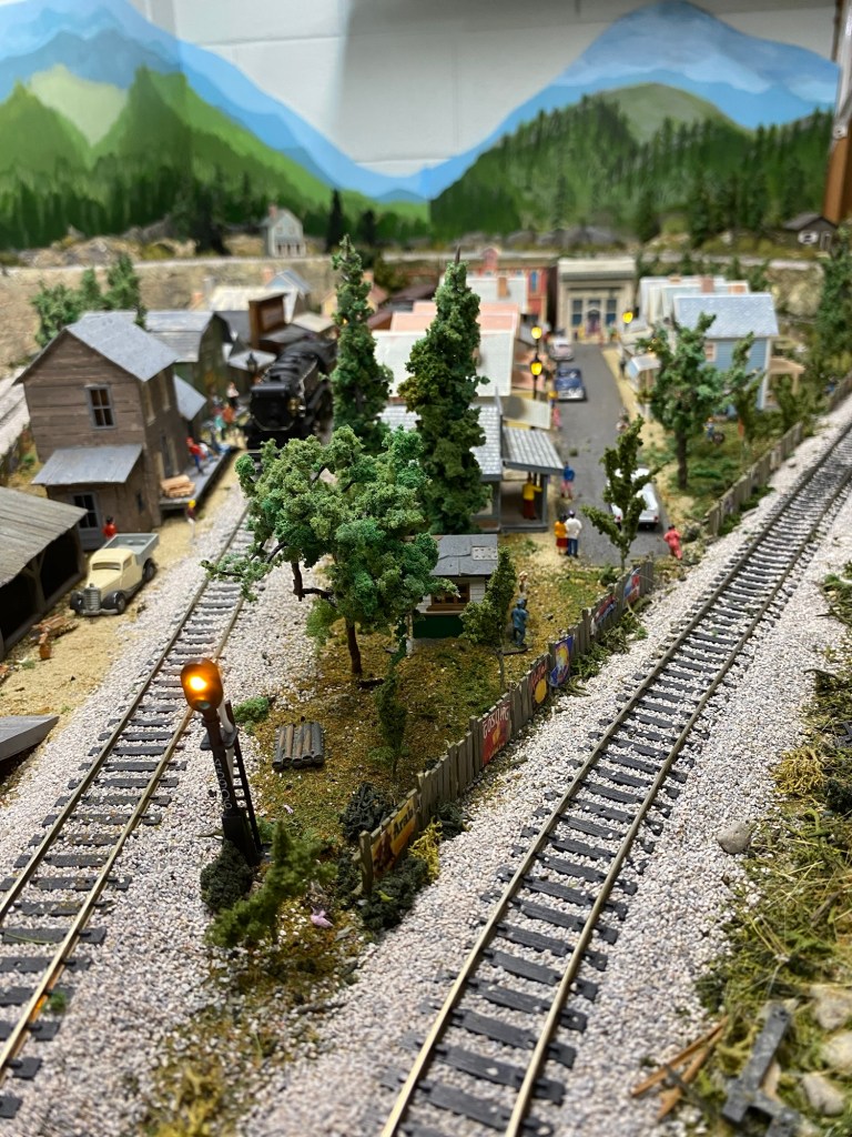
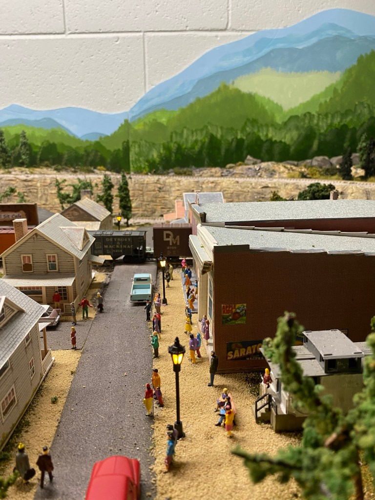

As I completed wiring under the layout, I also finished AC circuits for the streetlights in town and inside Maple Valley Manufacturing. The views on the inside of the factory are amazing, if I do say so myself. If you’re interested in seeing how I created the interior scenes, click here to read the post.
Building a control panel for the Maple Valley Model Railroad was a challenge, but I would do it again. Would I make changes? Yes. I would use a different material for the panel, use a bigger tape outline allowing more space for the DPDT switches, do a better job of isolating and anchoring wiring, and finally, not take almost six years to finish it.
