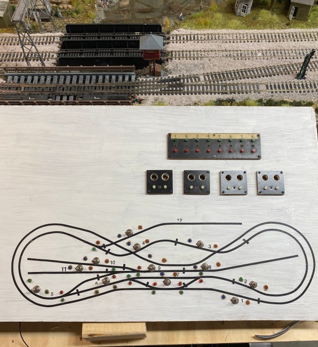
I have to admit, I have been working on my Maple Valley Short Line Model Railroad control panel for more than two years. I can run the layout just fine using Atlas Selectors to control power to the blocks, but I really want a panel with a layout diagram to make operations easier. Plus, I like lights and signals. Lots of them.
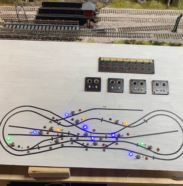
The face of the panel is 3/16″ wainscot material. I used 1/8″ artist tape for the layout diagram. Each turnout shown on the panel has a red and green LED to indicate whether the mainline (green), or the turn (red) is chosen. Power to the turnout LEDs is supplied through Atlas Snap Relays which also supply power to trackside signals. I am using vintage Acme Push Button Controllers for the turnouts.
If you are new to the hobby of model railroading, blocks are sections of track isolated by plastic rail-joiners, making it possible to switch off power to the block. This allows locomotives in adjacent blocks to run while a locomotive sits motionless in the block where power has been turned off. While it is possible to operate a simple layout without using blocks, you won’t be able to individually control more than one locomotive on the layout at a time.
Another important benefit of using blocks is that power can be provided by more than one source, making it possible to control two or more trains in different blocks at the same time.
On my layout diagram, numbered blocks are indicated by a cross piece of tape at the beginning and end of the block.
Two LEDs on each block indicate power and also which cab (power transformer A or B) is supplying it. To avoid having four switches on the panel for each block, two for DC power to the track, and two for AC power to the LEDs, I decided to use three-position-double-pole-double-throw (DPDT) toggle switches. One DPDT switch controls AC and DC power at the same time.
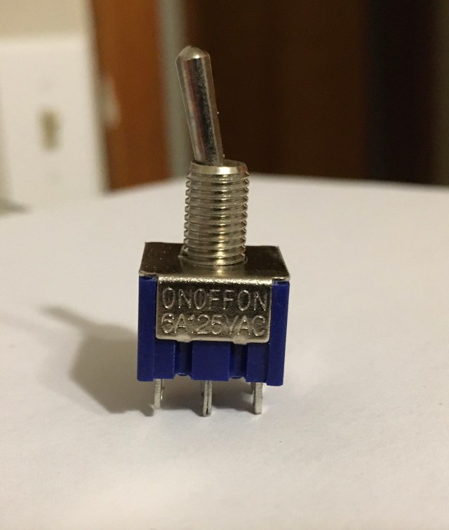
This is a three position, double-pole-double-throw switch. The middle position cuts power to the block. The switch has six contacts on the bottom, making it possible to use one side for AC and the other for DC current.
Understanding the wiring was a major obstacle and reason for dragging my feet. Plus, tremors in my hands make soldering difficult, but where there’s a will, there’s a way.
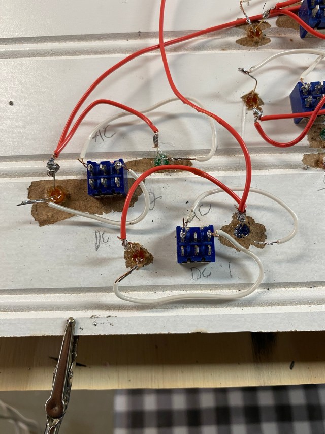
The positive contacts on the block LED are joined by a jumper wire, then wired directly to the positive terminal strip.
The negative LED contacts are wired to the outside switch contacts. The middle switch contact is connected to the negative terminal strip with wire and an appropriate resistor.
As I wired each DPDT and LED, I twisted two or three leads together and fastened them to the positive terminal block. With all the leads in place, I connected a resistor lead to the middle contact of each DPDT one at a time for testing by toggling the switch to each side.
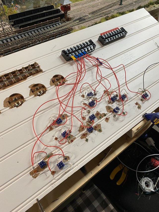
I soldered resistors onto several black wires and used them to connect the center switch contacts to the negative terminal block. Positive and negative leads from the AC power source will be connected to the strips, supplying power to each of the block LEDs.
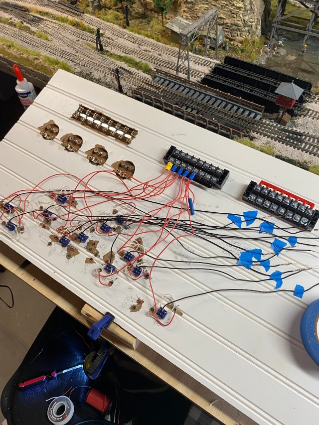
My plan to use a single DPDT for AC and DC current is half completed. My next project will be to connect the DC side of the switches to twelve blocks on the layout.
Work on the control panel for my Maple Valley Short Line Model Railroad is well underway.

Pingback: The Model Railroad Control Panel is Finished! – A Coffee State of Mind